Dunbar No. 1 Steam Engine
Picture 1
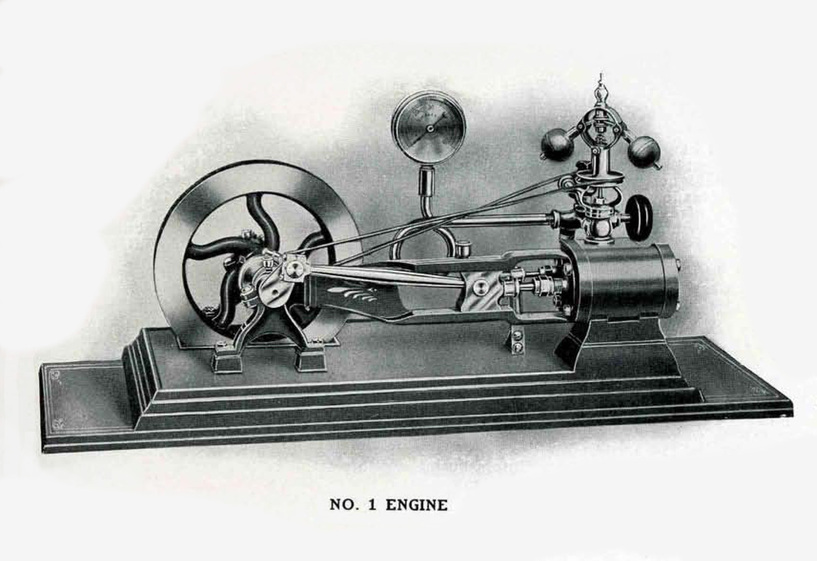
Dunbar Steam Engine No. 1 - Picture from Dunbar Sales Catalogs
Dunbar Steam Engine No. 1 - Picture from Dunbar Sales Catalogs
"The No. 1 Engine is used on our No. 1 wagon, Horse Wagons, and Sidewalk machine, to supply power for operating the popper and roasting cylinder. It is about 1/2 horse power, and will run all of the machinery on from 10 to 15 pounds of steam. The highest grade of material is used in the construction of these engines, and they are assembled by skilled workmen. This engine is very attractive, and the most perfect of it size ever placed on the market, being made on modern lines, the journals are made large to lessen the wear, and are adjustable. The main pillar boxes have babbitt bearings. It is fitted with a perfect working governor, which controls the speed of the engine. it has a lubricator for supplying oil to the cylinder. All polished parts are nickel plated, and the engine is mounted on a handsomely decorated japanned bed plate 24 inches long. Price of No. 1 Engine alone, $50.00." From the Dunbar Sales Catalogs.
|
|
Pictures 2 & 3
|
|
Pictures 4 & 5
Dunbar No. 1 Steam Engine
By Bruce Wm. Anderson
See Pictures below. More pictures and labels will be added shortly.
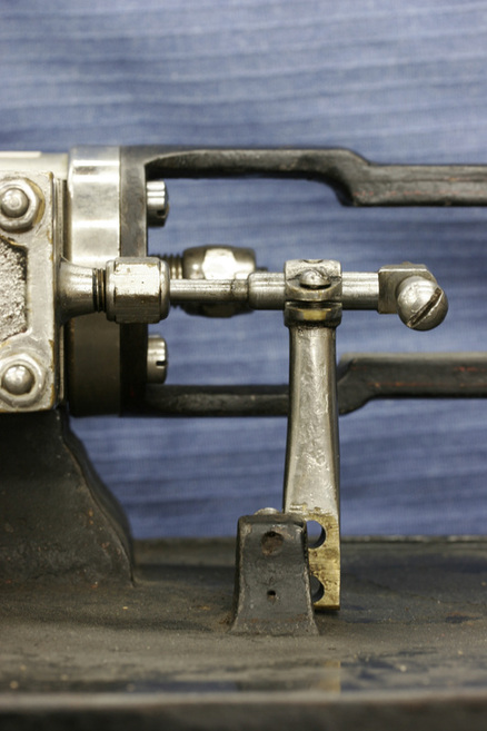
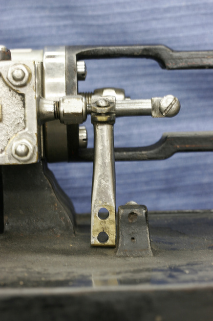
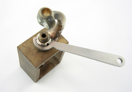
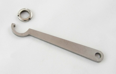
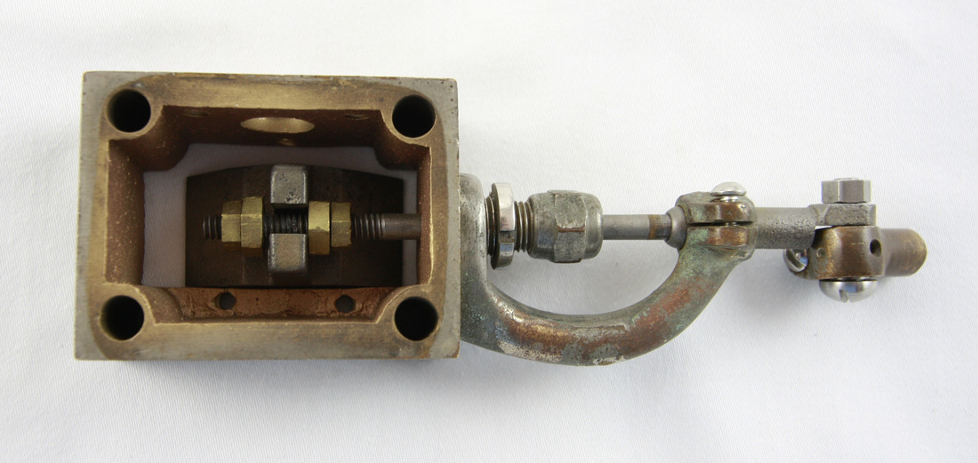
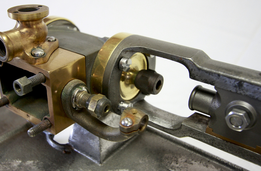
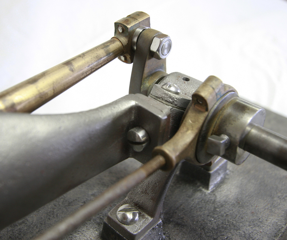
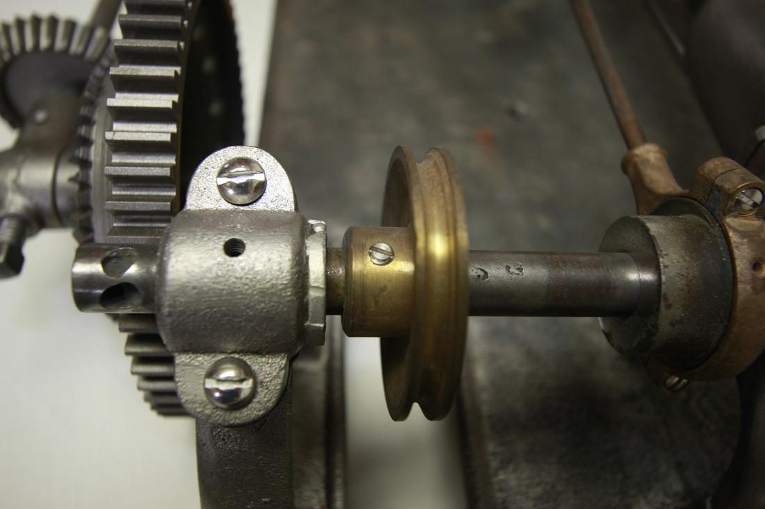
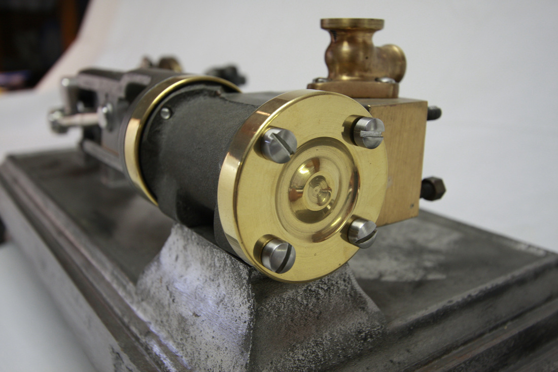
Dunbar manufactured two different sizes and types of steam engines: The Model 1 Steam Engine (Picture 1) had a sliding valve, was 1/2 horse power, had a bore of 1 1/4 inches, and had a stroke of 1 inch which gave it a displacement of .98 cubic in. (approximately 1 cubic in.). Ours runs at 12 to 14 pounds of steam pressure with an extremely free running steam engine and drivetrain. Early Model 1 Steam Engines had a sleeved governor and used a slide valve stem support that was bolted to a protrusion on the cast iron base Picturea 2 & 3). Later steam engines had a ball bearing governor and the slide valve stem support was attached to the steam chest by a second nut around the valve stem stuffing box (Picture 4). Note the spanner wrench that is necessary to remove this nut without damaging it (Pictures 4 & 5). Model 1 Steam Engines sold for $50.
Picture 6
|
Pictures 7 & 8
|
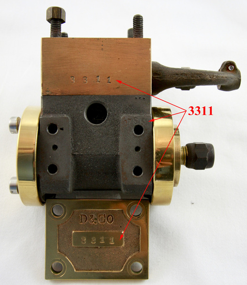
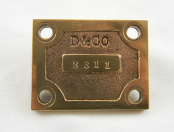
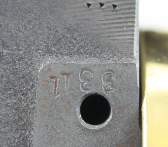
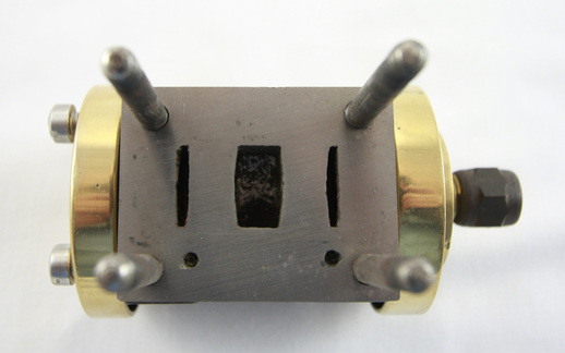
The serial number of the Model 1 Steam Engine was stamped on the valve chest cover, on the bottom of the valve chest (cannot be viewed without the help of a mirror or disassembly), and on the machined surface of the cylinder that is bolted to the elevated cast-iron cylinder support of the base (this cannot be seen without removing the cylinder from the cast-iron base). The numbers on the steam chest and steam cylinder may be the entire 3 to 4 digit number or may consist of only the last two digits in the number (Pictures 6, 7, & 8). If these numbers do not match or are not present then repair parts have been substituted.
The following information explains how we believe Dunbar numbered their steam engines. They started recording engine numbers at number 501 and then the engines are labeled consecutively up to 699. The next line, after 699, is listed as 2700 continuing consecutively to engine number 3339. All of the steam engines we have seen have been numbered between 538 to 694 and 2700 to 3336). Just like today, people rarely start a new checkbook at check # 1.
(Click here for a great story about engine 694 and its path to Australia - http://modelsteam.myfreeforum.org/archive/dunbar-popcorn-engine-no-694__o_t__t_37200.html) We feel Dunbar started numbering their steam engines at 501. They were in a big competition with Cretors and we wonder if they didn’t jump from 699 to 2700 as a marketing psychological ploy or a sales marketing tool? If anyone knows of any engine’s numbered between 1 and 500 or 700 and 2699 please share pictures of these with us and verify that the steam chest cover number matches the steam chest number and the engine cylinder number on the steam engine as described above. After reviewing Dunbar’s Steam Engine Registry Book we feel that approximately 855 steam engines were produced by Dunbar. At least 41 of the 855 Steam Engines were No. 2 Steam engines.
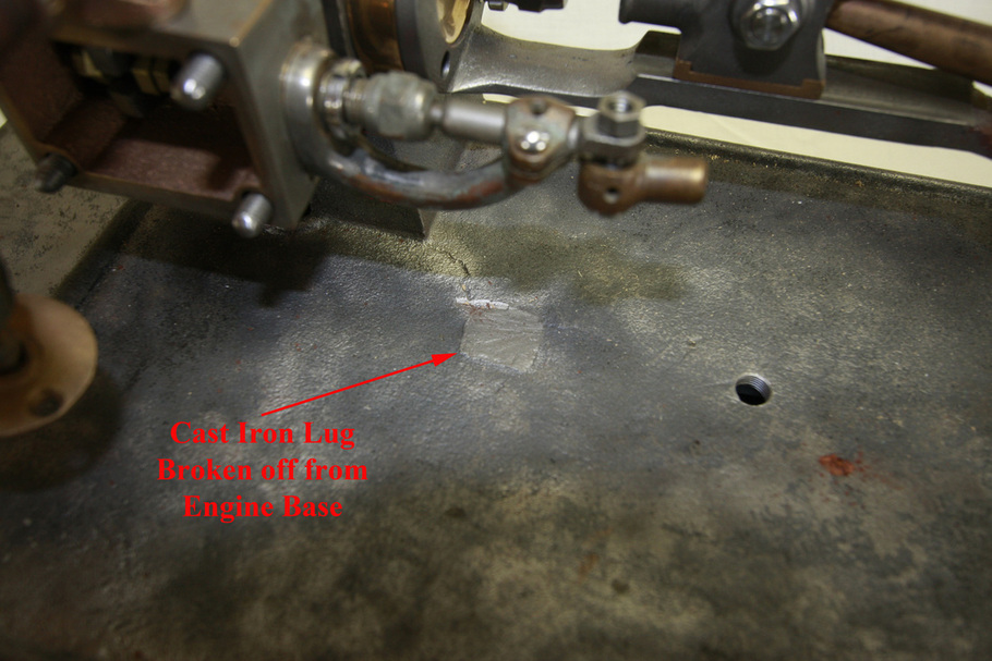
Picture 9
Engine number 576 which was produced in 1907 or earlier still had the cast-iron lug on the engine base to support the slide valve stem and had a sleeve governor. When the cast iron lug was no longer needed it was simply broken off the cast iron base and was smoothed over. Its outline can be seen in many bases with careful inspection. In later years the wood foundry pattern may have been modified to remove the cast-iron lug while still showing where the lug had been? Some bases show no signs of this cast-iron lug?
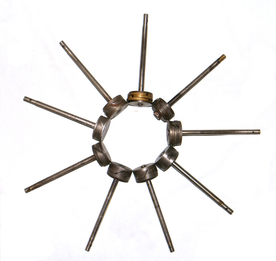
Picture 10
Dunbar Steam Engine Pistons as made by machinists through out the USA repairing Dunbar Steam Engines.
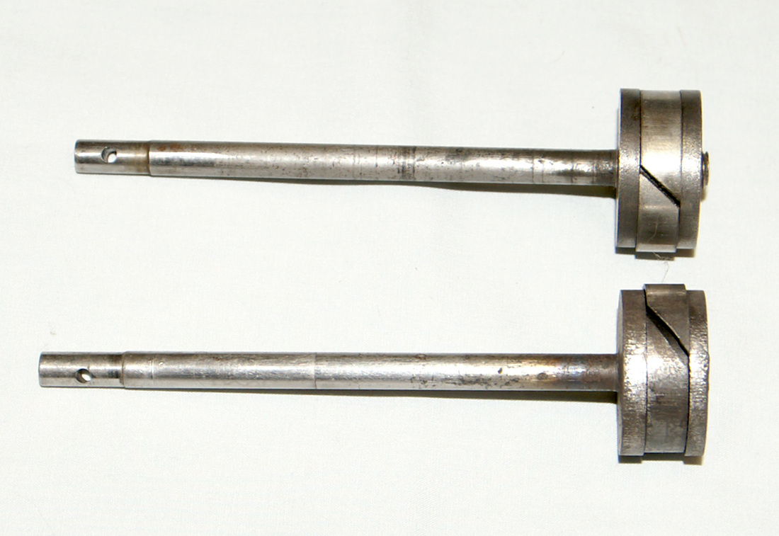
Picture 11
Two original Dunbar Pistons and Rings
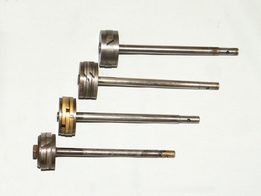
Picture 12
Note the differences in number and widths of the rings

Picture 13

Picture 14
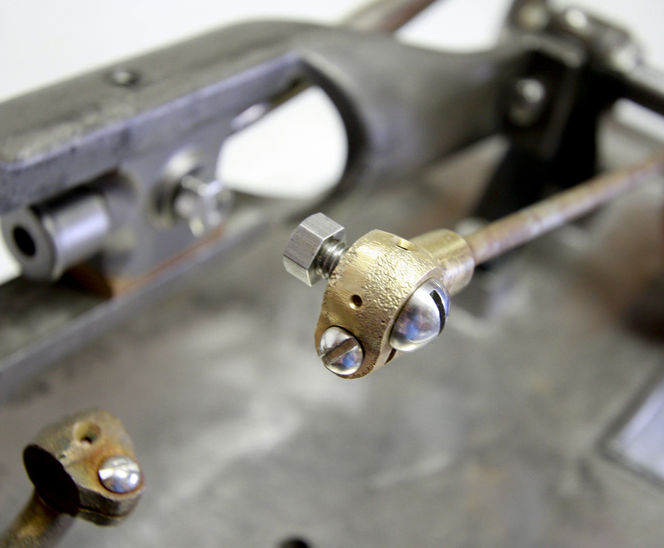
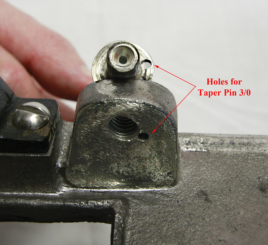
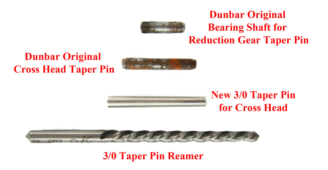
An original piston would have a 1 1/4 inch diameter with one cast-iron piston ring in one grove. The piston ring was 1/16 inch thick and .3125 wide with an outer diameter of 1.3125 (1 5/16 “) with a relaxed ring gap of .078 (5/64“) (Picture 11). We have compared pistons of 9 steam engines (Picture 10) and found two to be 1 1/4 inches in diameter with one cast-iron ring and both are identical in all other aspects (Picture 11). The remaining seven pistons were all of different designs and diameters of 1 ¼ inches or bigger. Therefore, we would suspect these other steam engines to have been bored out with new pistons made by machinists other than the Dunbar & Co factory. The reason to bore out a Dunbar Steam Engine is almost exclusively the result of the cylinder surface rusting due to being stored with water in the cylinder. This causes rust popouts which then damage the piston and its rings. When removing the piston rod from the crosshead be sure to realize the pin is a tapering pin (3/0 taper) and must be driven out in the correct direction (Pictures 13 & 14).
Picture 15
|
Picture 16
|
Picture 17
Picture 18
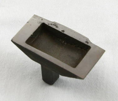
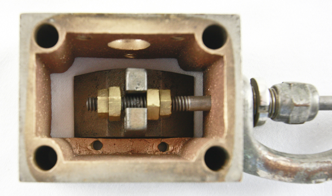
The slide valve often needs to be renewed on these engines (again due to rust) on both the cylinder valve surface (Picture 15) and the slide valve itself (Picture 16). Surface grinding the cylinder valve surface works exceptionally well to restore this surface as seen in picture 15. The slide valve can be resurfaced by laying a sheet of wet and dry sandpaper on a sheet of glass or other extremely smooth surface and polishing the surface down through the majority of the wear and rust. In picture 17 you can see the entire slide valve assembly. A close-up in picture 18 shows the timing adjustment nuts for the sliding valve.
Picture 19
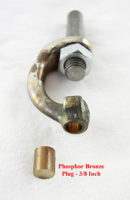
The later design slide valve stems support often has a significant amount of wear. The bearing surface can be renewed by removing the adjustment screw, bending opened the bearing, machining the old bearing surface to 3/8 of an inch in diameter inserting a piece of 3/8 inch phosphor bronze and silver soldering it in place, re-machining it out to its correct diameter slitting open the adjustment groove and finally redrilling and tapping for the adjustment screw. In picture 19 you will see a simple jig used to hold the support in the lathe for these machining procedures.
Picture 20
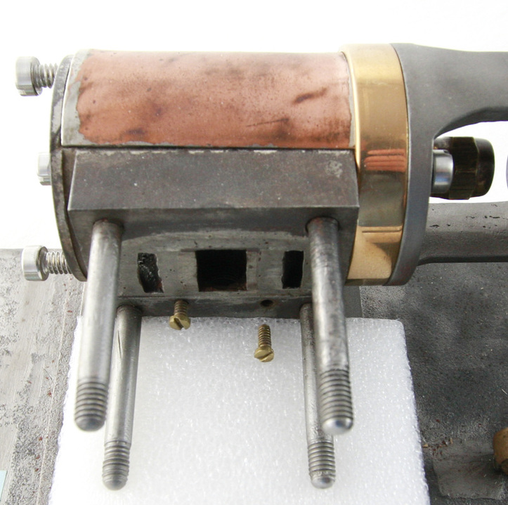
In picture 20 you will see two brass screws that were found holding the steam chest to the side of the steam cylinder. All No. 1 Steam Engines have the steam chest drilled for these screws. Most cylinders have centering holes for drilling and tapping for these screws. We are only aware of one engine that had these screws in place and that was approximately 400 engines into their 850 engine production. Were these screws added by someone after the engine left the factory? Did the factory originally plan on using pins to locate the steam chest?
Picture 21
Picture 22

Picture 23
Picture 24
Picture 25
Picture 26
Picture 27
Picture 28
Picture 29
Picture 30
Picture 31
In pictures 21 through 28 you will see the different fasteners with their correct heads used to assemble the No. 1 Steam Engine. This was determined by comparing over 20 Dunbar steam engines and noting which fasteners were the most commonly used on each component of the steam engine. In all cases it became very apparent what the factory used. In pictures 29 and 30 you will see the use of a tapered pin (Picture 31) to hold the reducing gears shaft in place where it is screwed into the lug on the base plate. This is present in some steam engines and not others but remember it’s a tapered pin and must be driven out the right way. We feel the taper pin was not necessary on the Steam Engines where the power takeoff runs perpendicular to the crank shaft. Picture 22 shows this arrangement
Picture 32
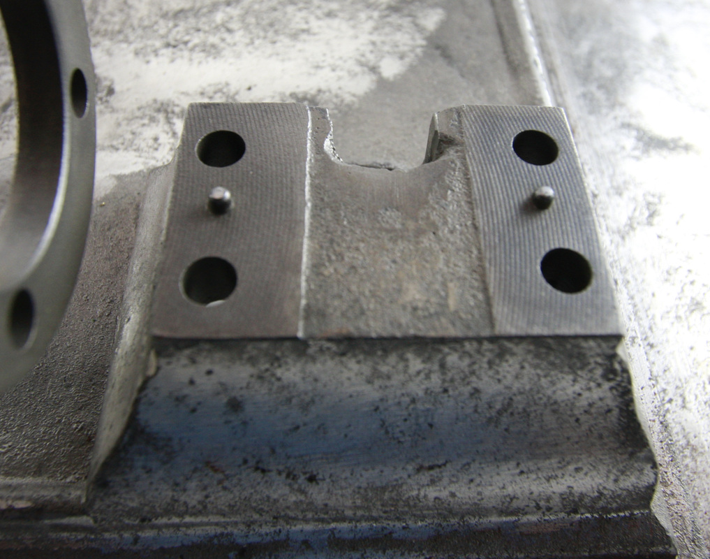
The steam cylinder is bolted to the cast-iron base with 4 filister headed screws. The cylinder is aligned with two pins that are placed in the cast-iron base (Picture 32).
Picture 33
|

Picture 34
|
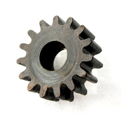
In picture 33 you will see the fiber drive gear that engages with the cast-iron reduction gear of the No. 1 Steam Engine. These were a very commonly purchased replacement item for these engines. I am unsure if the fiber gear was used instead of a cast-iron gear for noise reduction in the gear train or providing a type of sheer pin in case of extreme stress to the gear train? In picture 34 you will see a fiber drive gear that is split in the area of the set screws which is extremely common in these older engines.
Picture 35
|
Picture 36
|
Picture 37 - Will be added later
Picture 38
Picture 39
Picture 40 - Will be added later
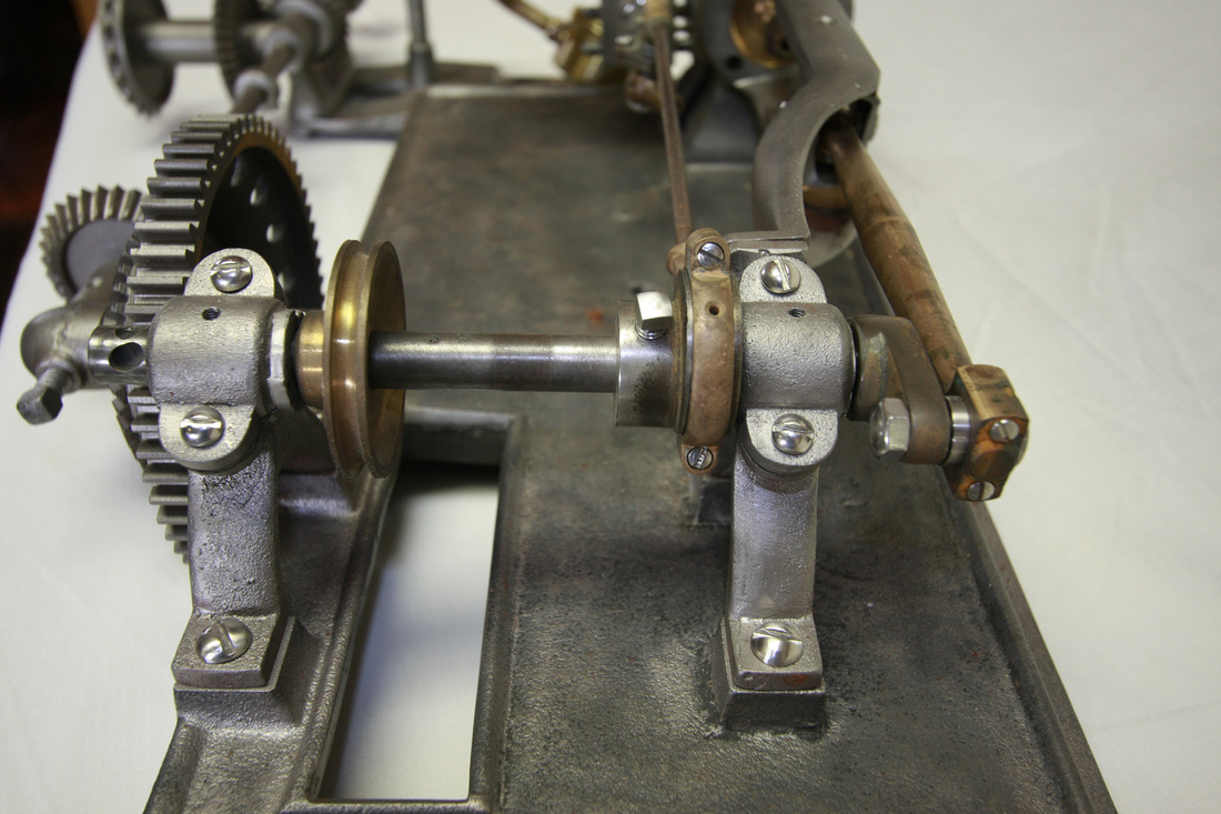
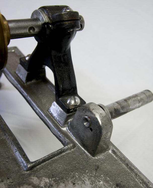
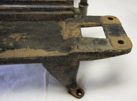
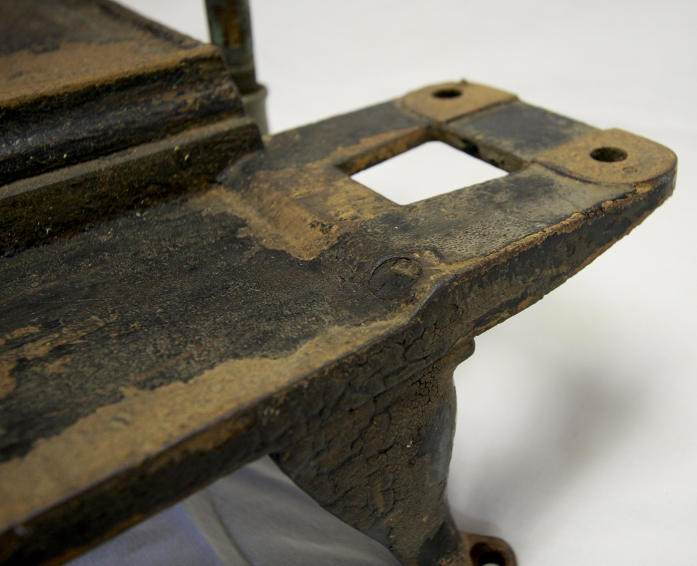
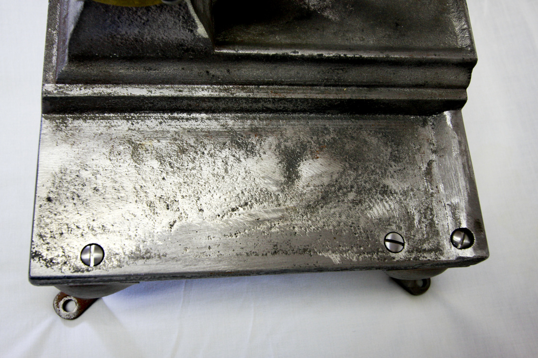
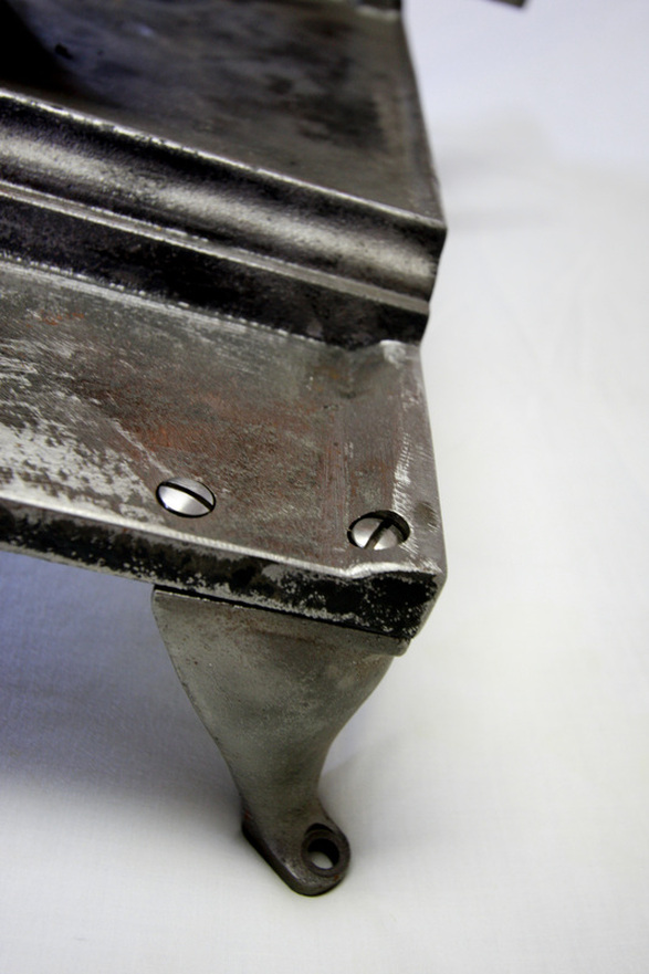
No. 1 Steam Engine bases vary from machine to machine. The larger machines had a full base with two wings and 4 legs bolted underneath these wings. The shaft for the large gear is kept from rotating by a tapering pin (3/0 taper). The base plate was cast with a cast iron projection to support shafting running parallel with the piston (Pictures 35 & 36). On very early steam engines with this shafting configuration a steel support was bolted onto the cast-iron base to provide support for this shafting (Picture 37 will be added later). When this projection was not needed it was sawed off (Pictures 38 & 39) Finally, the cast-iron base is found with the wings sawed-off and no legs (Picture 40 will be added later). This may be a modification made by people preparing the steam engine for display after being removed from a popcorn wagon as we have not observed an original popcorn wagon with this base configuration in use.