Dunbar Steam Engines Governors
By Bruce Wm. Anderson
The pictures are located above the paragraph they are first mentioned in.
Dunbar & Co used a governor of their own design on their No. 1 Steam Engine. The governor controls the revolutions per minute (RPM) of the steam engine. The importance of this is that the poppers must turn at 21 ½ to 26 revolutions per minute to properly pop popcorn and this is controlled by the revolutions per minute (RPM) of the steam engine. The steam engine revolutions per minute (RPM) can be set by either measuring the number of revolutions per minute (RPM) of the poppers or using an RPM gauge off the end of the crankshaft of the steam engine. According to a letter written to Mrs. Peterson (an owner of a Model Four Auto) by Dunbar & Co, the 12 (depth of cylinder) by 15 (diameter of cylinder) inch Dunbar Rotary Air Poppers should turn at 26 revolutions per minute. (In the large auto units the gear reduction between the steam engine and the poppers was 16:1; therefore, the steam engine RPM would be 416.) This is by far the most common size popper used in the early Dunbar Model 4 Automobiles and Horse-Drawn Wagons. Recently, an early electric motor driven 12 by 15 inch Dunbar Rotary Air Popper was timed and it turned at 23 revolutions per minute. The electric popper's RPM cannot be varied and may have been influenced by the available off the shelf drive components of the day. Dunbar Manufacturing presently uses 21 1/2 RPMs for their Celebrated Rotary Air Poppers but they are all 20 to 36 inch diameter Rotary Air Poppers and they do not presently make a 12 by 15 inch Rotary Air Popper. As the cylinder diameter increases the revolutions per minute (RPM) of the cylinder would need to decrease to provide the same linear speed of the outer screen passing the raw corn over the open flame or electrical resistant element. So it makes sense that the 12 by 15 inch Rotary Air Poppers use the faster speed of 26 revolutions per minute (RPM) and that the larger Rotary Air Poppers use the 21 1/2 RPM. If the Rotary Air Popper revolutions per minute (RPM) is too slow there is an increased chance of fire within the popper. If the revolutions per minute (RPM) of the popper is too fast you will see an increase in raw corn throw-out from the front of the popper.
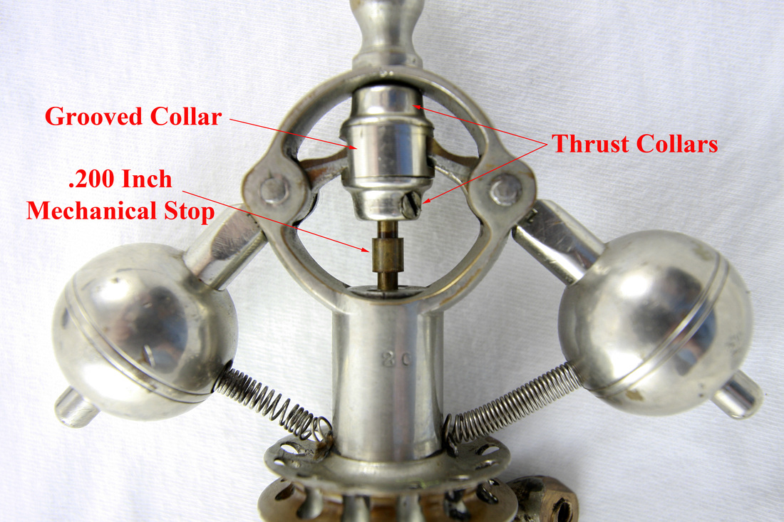
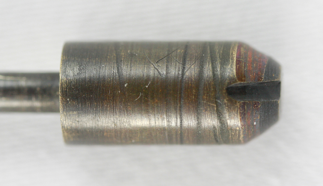
Picture 1 - Mechanical Stop used with Style B Throttle Valve
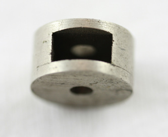
Picture 2 - Grooved Collar
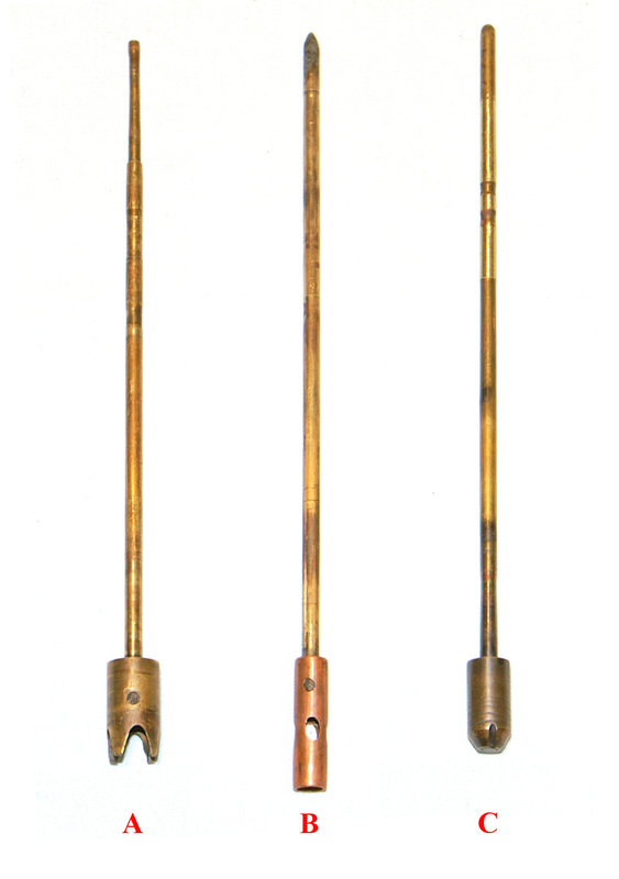
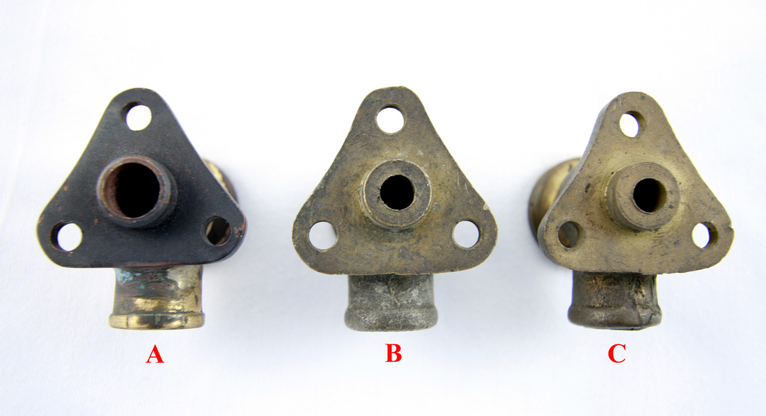
Picture 3 - Three Styles of Dunbar Governor Throttle Valves
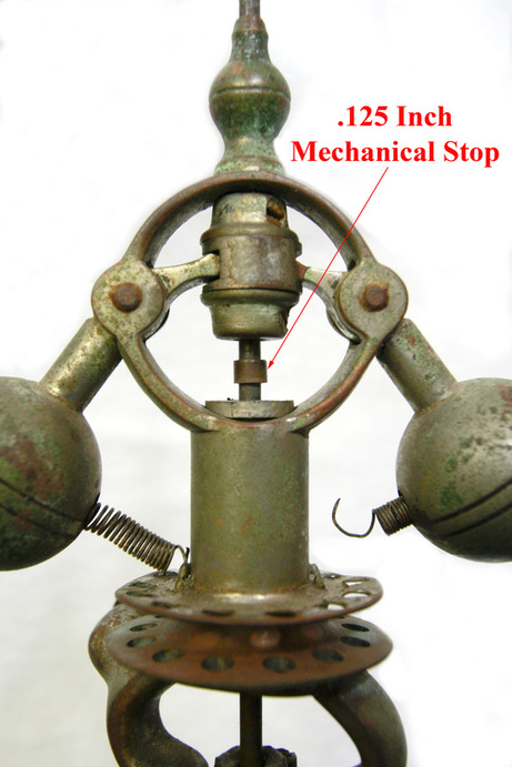
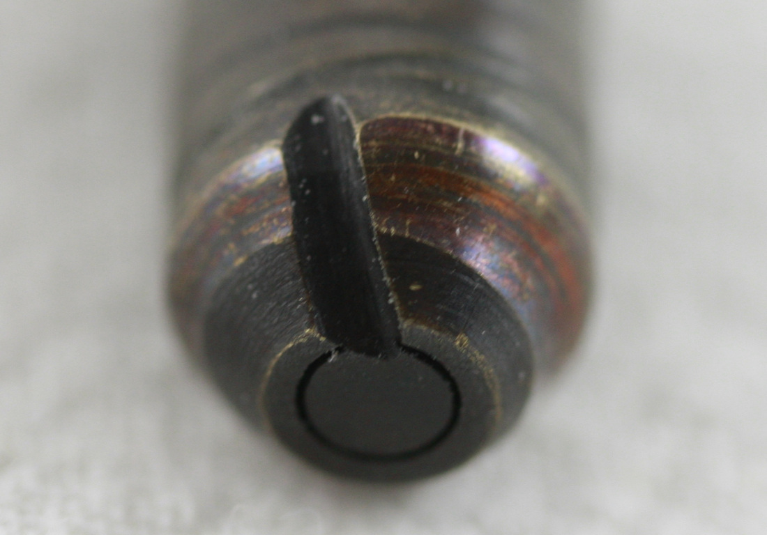
Picture 4 - Mechanical Stop used with Style A Throttle Valve
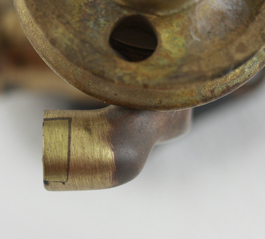
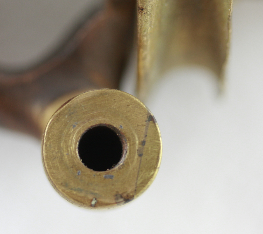
The adjustment for the steam engine’s revolutions per minute (RPM) is accomplished by loosening the two small set screws, one in each of the thrust collars which are located on the governor throttle valve stem on either side of the grooved collar. Moving the two thrust collars and grooved collar up you will result in the steam engine running at a lower RPM and by moving them down the steam engine will run at a faster RPM (Picture 1). This grooved collar is inserted by the governor ball balance arms that are on the opposite side of the pivot pin of the governor ball (Picture 1 & 2). As the governor balls move in and out due to centrifugal force of the balls and the counterbalancing force of the two closed springs (or the tower spring on very early governors) the grooved collar raises and lowers the 1/8 inch throttle valve stem. This throttle valve stem runs down the center of the governor and is attached to a sliding throttle valve that controls the volume of steam entering the engine. Three different designs of sliding throttle valves are known to exist. Which design is used may be determined by looking at the outside of the governor. The earliest governor which has a sleeve bearing, we believe had only one style of valve (Picture 3). Small brass mechanical stops (tube sleeves) are used on some of the governors that may tell us what type of throttle slide valve is used? The style A governor throttle valve stem uses a .125” tall (Picture 4) mechanical stop made of brass tubing that is .125” inside diameter and .187” outside diameter. The style B governor throttle valve uses a .200” tall (Picture 1) mechanical stop made of the same brass tubing. These mechanical stops are placed just beneath the adjustable thrust collars, which are on either side of the grooved collar. The mechanical stops are missing on many present day Dunbar Steam Engines. The third throttle valve style C, is of a needle valve design and the stop is provided by the seating of the needle valve.
Picture 5
Picture 6
Picture 7
Picture 8
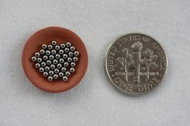
Picture 9 - 44 1/16 Inch Ball Bearings
Picture 10 - Governor Ball Bearing Assembly
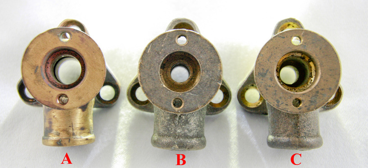
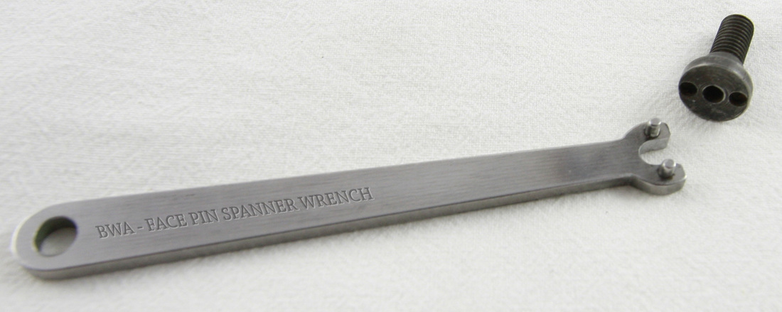
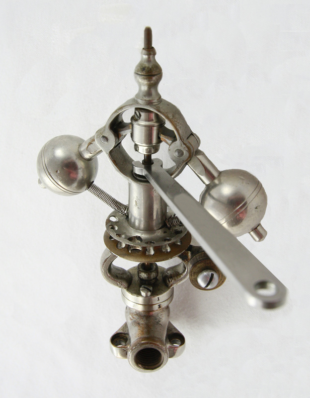
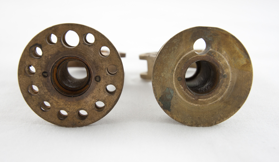
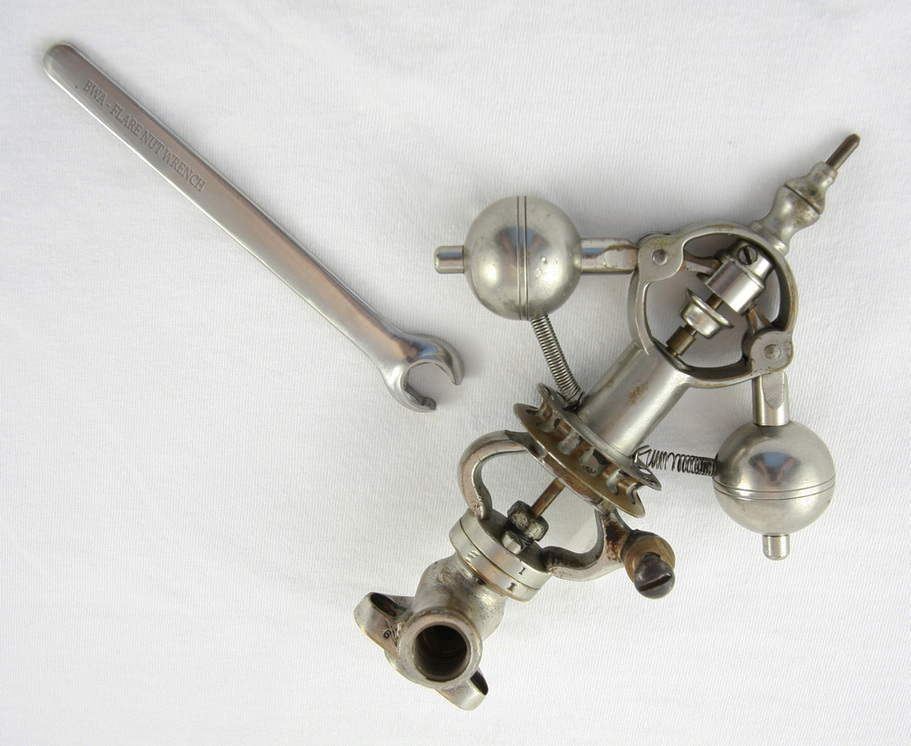
The throttle valve body (governor base) is also machined internally differently for each of these throttle valves but looks identical externally on its assembled surfaces. You will note in picture 5 and picture 6 that style A and B of the throttle valve bodies have continuous holes of the same diameter (starting below the 1/4" recess as seen in picture 5) while the style C throttle valve body has a different diameter hole on the top and bottom (Picture 5 & 6) and has a tapered seat for the needle throttle valve (Picture 3 - Style C). In pictures 7 and 8 a face pin spanner wrench (made by Bruce Wm. Anderson) is shown. At this time, a Dunbar produced face pin spanner wrench is not known to exist. This face pin spanner wrench is necessary to properly take apart, reassemble, and adjust the ball bearing and sleeve bearing governors. When reassembling the governor the ball bearings should be held in place in the races by a thin coat of grease. 20 ball bearings are required in the top race and 24 in the bottom race. Caution should be exercised when disassembling the ball bearing governor as the 44 --1/16-inch balls (Pictures 9 & 10) are not contained in a ball bearing retainer but are loosely placed within the bearing races. They will spread themselves evenly to all corners of the room if not contained! (Don’t ask how the author knows this!)
Pictures 11 and 12 - Throttle Needle Valve - Style C
The sliding throttle valves are seen in Picture 3. Style A, B and C require mechanical stops to maintain a small flow of steam at low RPMs. Style A and B used a brass tube mechanical stop (Picture 1 & 4) to maintain a minimal throttle valve opening while style C has a groove in the needle valve serving this same purpose (Picture 11 and 12). Therefore, all three throttle valve styles allow a slow flow of steam at low RPM to prevent the steam engine from locking up?
Picture 13 - Picture will be added later
Picture 15
Picture 16
Picture 17
 Picture 14
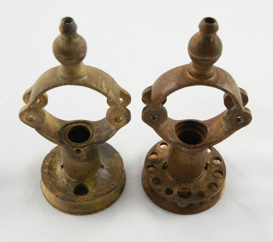
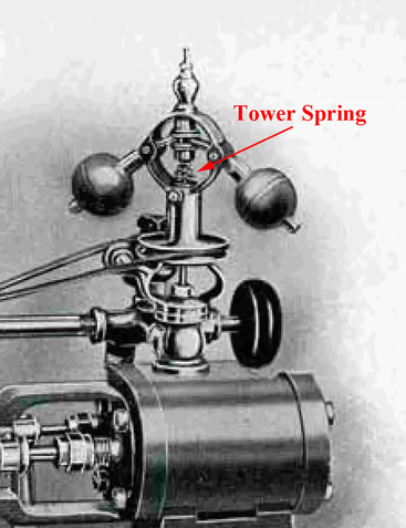
The first Dunbar Governor was a sleeve-bearing governor. Few sleeve-bearing governors exist today. This is probably due to the sleeve-bearing governor being replaced by the ball bearing governor as the sleeve bearing governors wore out (The author’s Model Four Auto is known to have had at least three different ball bearing governors over 50 years of use and of course the sleeve bearing governors would have had a shorter life). The earliest of the sleeve bearing governors had three identifying features. The first was a counterbalance tower spring that had the throttle valve stem passing through it instead of the two counterbalanced closed coil springs. We are aware of one example of a governor with this feature (Picture 13 will be added in future) and it can be plainly seen in the No. 1 Steam Engine picture in the Dunbar Catalogs (Picture 14). The second identifying feature was the governor’s leather belt drive pulley that had only one vertical hole to remove the screws that held the governor standard’s bearing assembly to the valve chest or base (Pictures 15 & 16). The third identifying feature is an oil hole at the top of the standard’s bearing assembly (Picture 17). The standard’s bearing shaft is 1/2 “ in diameter and brass. The sleeve is steel.
Picture 18
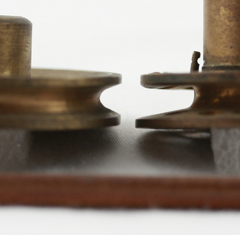
Picture 19
Picture 20
Picture 21 and 22
Picture 23
Picture 24 - Left Governor Pulley Worn by 3/16 Inch Leather Belt
Right Governor Pulley Worn by Incorrect Narrow Belt
Right Governor Pulley Worn by Incorrect Narrow Belt
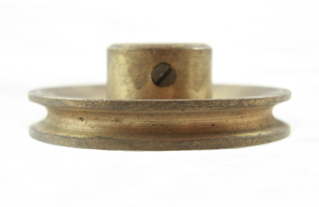
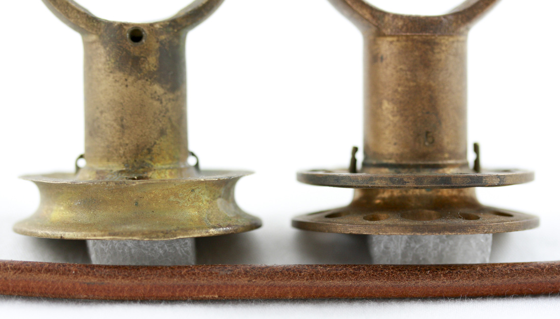
Picture 25 - Left Picture is the Profile of an Unworn Pulley
Right Governor Pulley Worn by Incorrect Narrow Belt
Right Governor Pulley Worn by Incorrect Narrow Belt
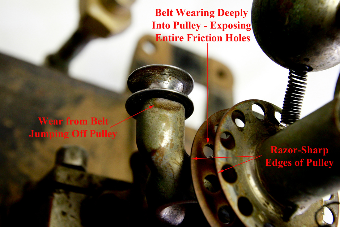
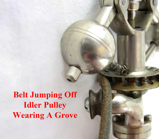
When new, the governor’s drive pulley had a 3/16-inch diameter half round belt groove with a 1/16 inch flat on each side of the belt groove (Picture 18 - example of belt grove outline). The governor pulley has a 1.537” lower face outer diameter and 1.474” upper face outer diameter with one vertical screwdriver hole to remove the fillister headed screws holding the standard’s bearing assembly to the throttle valve base. The later governor's pulley had the same dimensions with a series of 12 vertical friction holes and one screwdriver hole that just perforated the bottom of the leather belt groove (Pictures 15 & 17). As the belt wears the pulley down through the friction holes the pulley sides wear razor-sharp (Picture 19). Eventually, the top side of the pulley groove wears through the top pulley side and the topside of the pulley becomes a loose washer. As the belt wears into the governor drive pulley the belt will tend to jump out of the idler pulley (.625” OD) on the governor and wear the top of the idler pulley support (Pictures 19 & 20). The only solution for this is to machine off the worn out governor drive pulley and silver solder on a newly machined pulley (in the future these may be available from Docs’ Popcorn Company, Bruce and Darlene Anderson). The idler pulley support can be renewed by machining off the worn portion of the idler pulley support and silver soldering in new brass (Pictures 21 & 22). As the governor pulley’s groove wears to a smaller diameter the governor increases its RPM in relation to the crankshaft’s RPM. The use of a long spring, a large O-ring, etc. instead of a 3/16 inch leather belt spliced with a wire staple (Pictures 23 & 24) will lead to faster wear of the governor drive pulley, the governor idler pulley and, the crank shaft governor drive pulley as they are not 3/16 inch in diameter and only wear the bottom groove of the pulley (Pictures 24 & 25).
Picture 26 - Extremely Worn Throttle Valve Stem
Picture 27
Picture 28
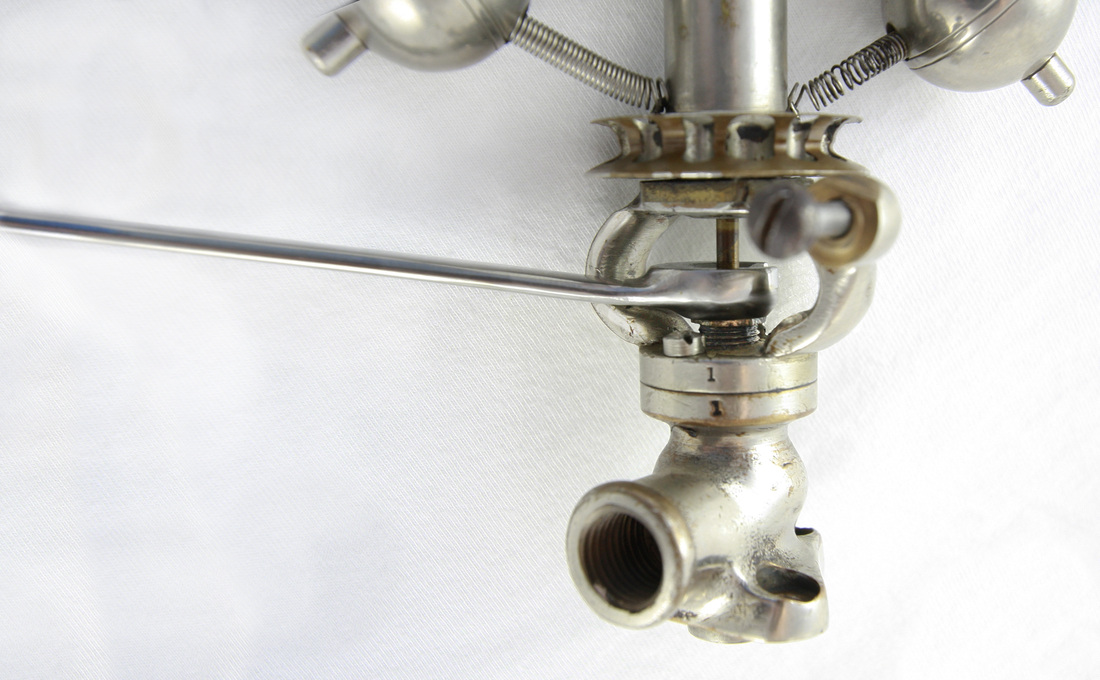
The throttle valve stem wears were the packing gland nut and packing rubs on it (Picture 26 - A) and this will require the throttle valve stem to be replaced on most governors to stop the leakage of steam. This sliding throttle valve stem is a 1/8 inch brass rod. If you tighten the packing gland nut to stop the steam leakage with a worn throttle valve stem the throttle valve stem cannot move freely and the governor stops working. The use of a modified flare nut wrench (craftsman wrench with the bottom side contoured to not interfere with the fillister screw heads) will greatly facilitate this adjustment (Pictures 27 & 28). If the throttle valve stem is worn in the top half (Picture 26 B, C, & D) it indicates worn or poorly adjusted bearings in the governor’s standard bearing assembly, a bent governor’s standard, a bent throttle valve stem, or a combination of any of these.
Picture 29
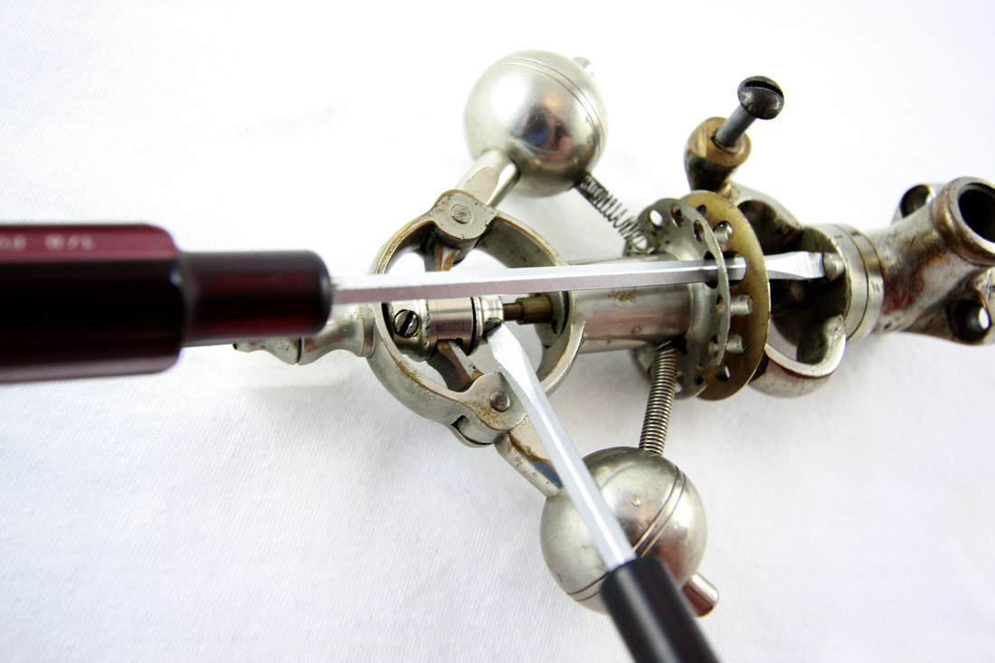
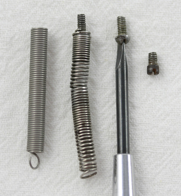
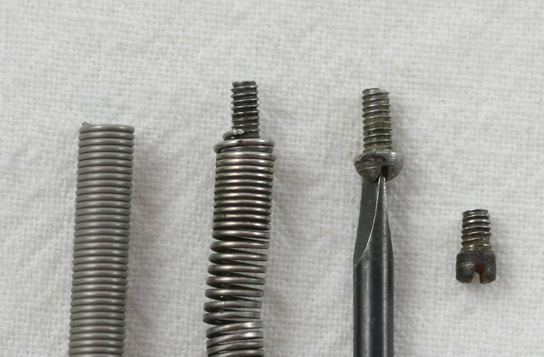
Fillister head screws are used to mount the governor base (throttle valve body) to the steam chest. If the two counterbalance springs need to be removed or replaced it should be noted that they are held in the governor balls by a single very small round or fillister headed straight slotted screw (thread 2-56 and length 1/8-3/16”). Pass a jewelers screwdriver through the center of the spring and use the biggest blade size possible to engage the slot (Picture 29). You only get one chance to do this so…..don't strip out the screw head! These counter balance springs are held to the standard by two brass pins of approximately .058” - .060” (16 gauge wire is .063”) bent in to form a hook. These hooks are seen in Pictures 15, 17, 24, & 25. In picture 15 you are seeing the bottom of the pin. These two closed coil springs are .158” outside diameter, 50 coils, and made of .019 stainless steel wire. Originally, these were made of spring steel, but by using stainless steel you will save the expense of nickel plating them.
