Dunbar's White Gas Systems
by Bruce Wm Anderson
The reconstruction of this white gas system was made possible by: John and Bev Mueller's donation of a collection of white gas parts, white gas parts from Bruce and Darlene Anderson's Model 4 Auto, information gathered from the Columbus, Wisc. 1200 Dunbar, Bruce Anderson's chance spotting of a Gloria Light Co. tank under a trailer at the Hershey Swap by recognizing the tank cap and then the internet search for the Gloria Light Company, a donation of a Dunbar gas vapor generator and mantle light pressure gas tank (divided) by Bob Babcock and especially The Dunbar Operating Instructions from Dunbar Mfg. Company.
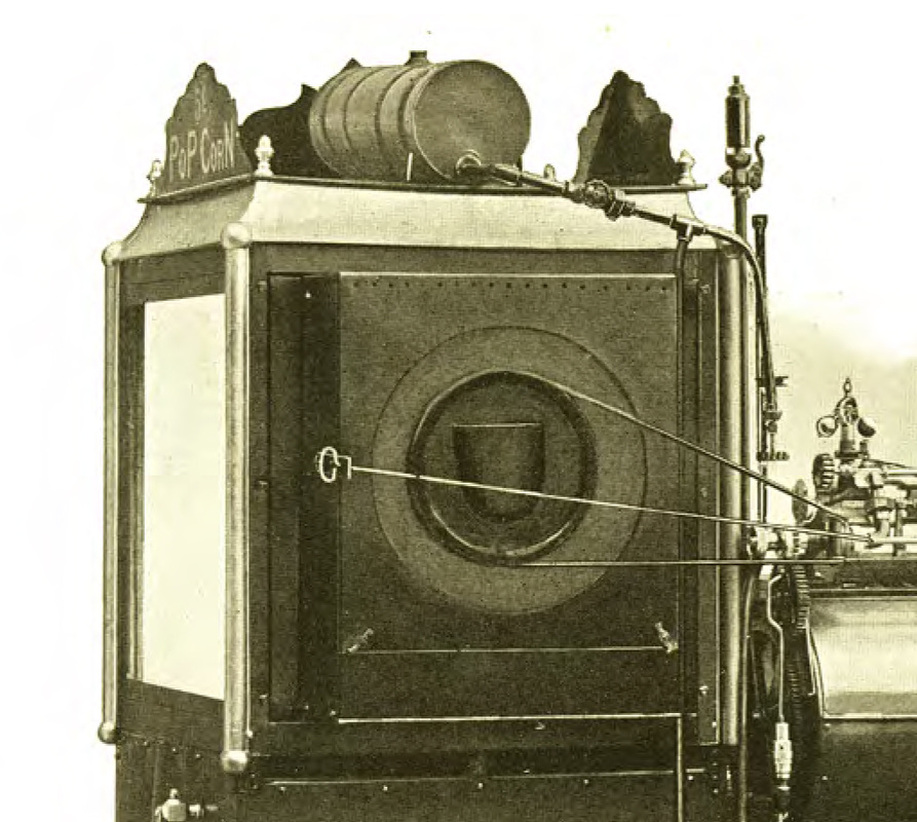
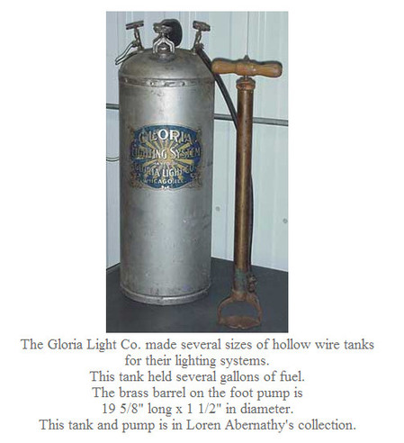 Photo from the Terrence Marsh Lantern Gallery - Picture 1
White gas (Naphtha or Coleman Fuel) was used as the fuel for all the early steam engine powered popcorn wagons. The pressure gas feed component of the Dunbar & Co white gas system that delivered the liquid gasoline to the gas vapor generator or mantle light system was an adaptation of the Gloria Light Company, Chicago, Illinois Hollow Wire System (Click on this link to see an explanation and pictures of a hollow wire system at the Terrence Marsh Lantern Gallery ) The link will open in a new tab or page. (It is interesting to note that in the early years of Dunbar & Co they advertised to install these Hollow Wire Systems in homes to supplement the income of the new fledgling Dunbar and Co.) Dunbar’s accounts payable books, that are available as early as 1913, show regular purchases (10 full pages of purchases from Gloria Light Co) from 1913 to mid-1930. Hollow Wire Systems were developed for hydro-carbon lighting devices (mantle lights) which were used in homes and businesses of the late 1800's and early 1900’s. Many homes were plumbed for gas lighting and wired for electric lighting as people were unsure of the future of electricity. Dunbar & Co Popcorn Wagons could be ordered with electric lights, mantle lights or both. Electric Lights were first pictured in the 1907 Catalog. The hollow wire referred to a 1/8 inch thick walled copper tube that went from the gas tank to the gas vapor generator. In a home or popcorn wagon, this gas vapor generator would have been a mantle light fixture or a large gas vapor generator. Both were used in the Popcorn Wagons. The Popcorn Wagon’s gas vapor generator was located in the boiler compartment underneath the boiler and distributed the gas vapor through burner tips (or jets in today’s gas systems) and then through air/gas mixing tubes.
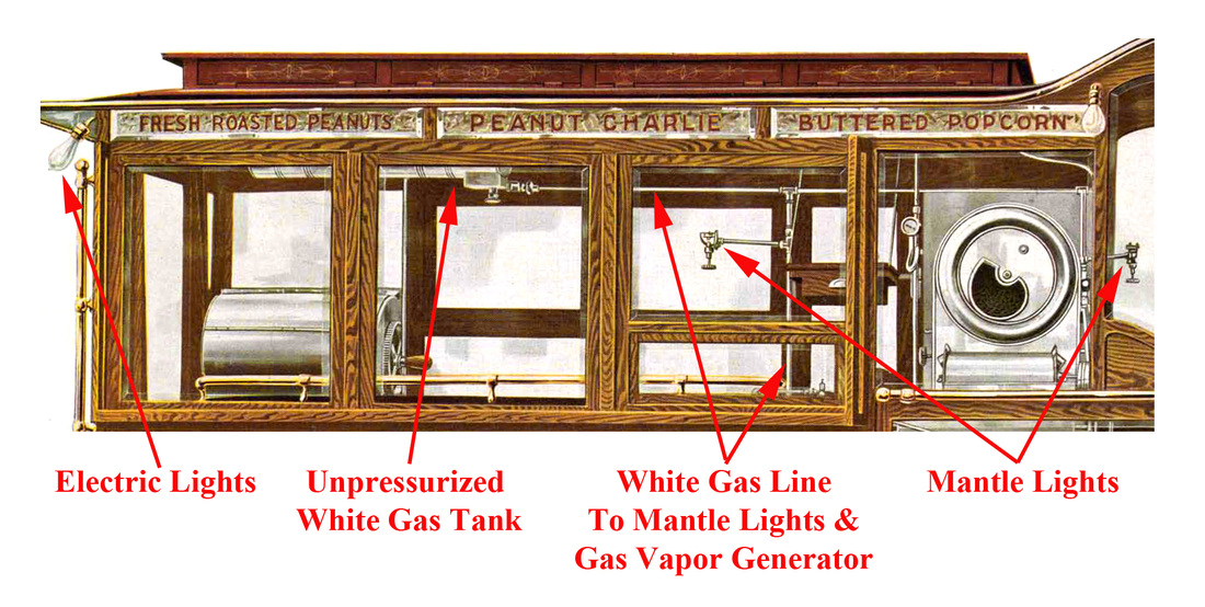
Picture 2 - Unpressurized White Gas Tank on Top of Dunbar Popcorn Wagon
Picture 3
Picture 4
Picture 5
Picture 6
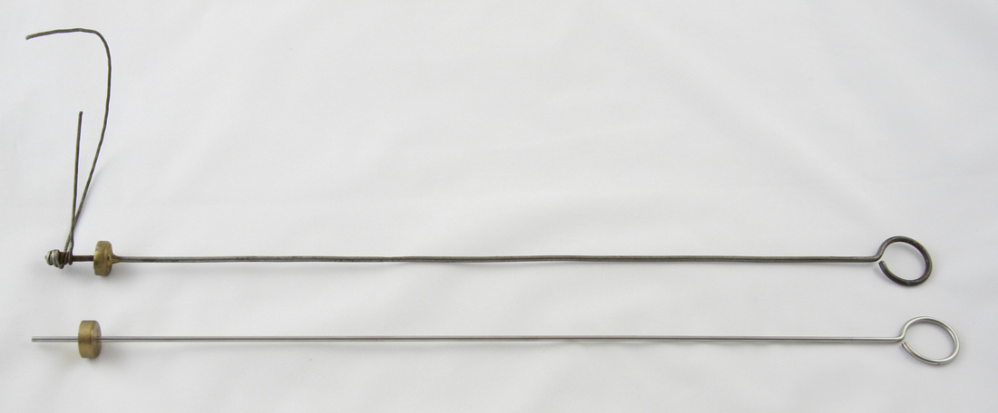
Picture 7 - Upper Original Lighter Should have Two Layers of Coiled Wire - 16 Gauge
In this picture the wire is uncoiled. Lower Lighter is a partially done reproduction.
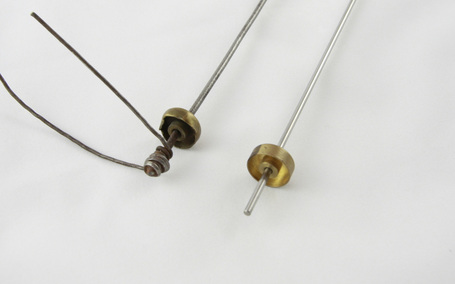
In this picture the wire is uncoiled. Lower Lighter is a partially done reproduction.
Pictures 8 & 9
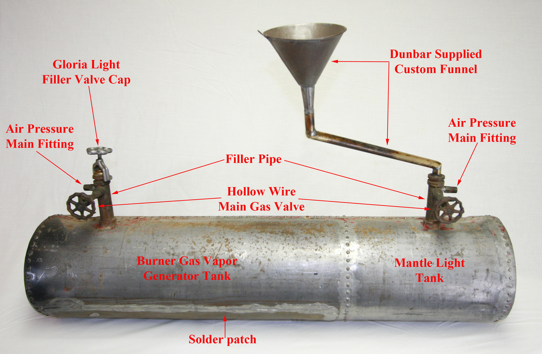
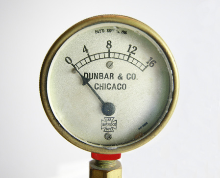
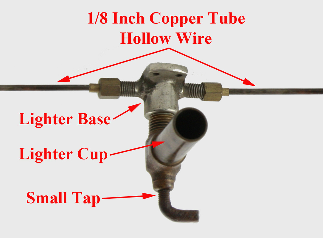
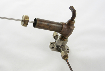
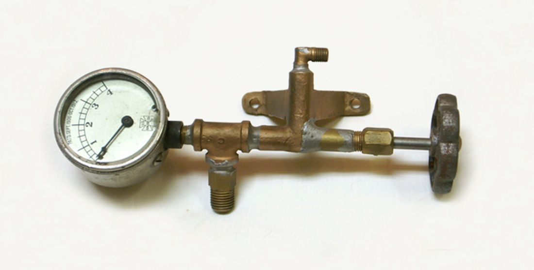
THEORY OF OPERATION: Dunbar had two different white gas systems. The first simpler system was fed by an unpressurized tank that was placed either on the top of the popcorn wagon roof (Picture 2) or just under the roof and inside the popcorn wagon (Picture 3). The tank had a ¼ inch Crane needle valve that was used as the main gas shut off valve and ¼ inch iron pipe was used to feed the gas vapor generator, the lighter, and the mantle lights. The cap on this unpressured tank was vented. These simpler systems were uses on all early wagons, early gas store models, and later just on the No. 1 and No. 2 Wagons. The second white gas system was a pressurized system. White gas was poured though a filler pipe (Picture 4), often with the use of a Dunbar & Co modified funnel (Picture 4), into an unvented tank and then the airtight tank cap was replaced (Picture 4). This filler pipe had two copper tubes attached to it. The first filler pipe tube was a 1/4 inch copper tube that was used to supply air pressure to this tank from a remote location, usually inside the popcorn wagon. In these pressure systems a Schrader tire stem thread without the valve was used to attach a hand operated pump. Either a tire pump (vehicle supplied tire pump) or the Gloria Light Company’s supplied tire pump (Picture 1) and also pictured in the above website could have been used to pressurized the tank. There is a US Gauge (the dial is labeled with Dunbar & Co) that reads 0 to 4 pounds for this gas pressure system. We also have an original Dunbar labeled gauge 0 to 16 pounds (Picture 5) which probably was used for this application for the mantle lights system? These gauges record the air pressure in the white gas tank and 2-3 pounds was the recommended pressure used to propel the white gas to the gas vapor generator. The second filler pipe tube originates at the bottom of the gas pressure tank and travels to the main gas shut off valve located on the side of the filler pipe and it becomes a 1/8 inch copper tube (hollow wire) which travels to and through the lighter base (Pictures 6 & 9). The lighter base has a small tap (L-shaped thumbscrew needle valve) which is used to fill the lighter cup (Picture 6). This allowed the lighter (Pictures 7 & 8) to be stored in (Picture 9) and also redipped into the gasoline and then lit with the gas generator burner flame so that the lighter could be used to transfer the light (flame) to other burners. These systems had no traditional pilot light. The gas vapor generator flame served as the pilot light as it was lit whenever the popcorn wagon was in use. Upon leaving the lighter base, the hollow wire is directed to the boiler compartment and attaches to the gas vapor generator through the gas vapor generators valve. This valve is used to regulate gas pressure and has an L-shaped thumbscrew. To generate the gas vapor, liquid gasoline must be allowed to flow into the drip cup of the gas vapor generator by slightly opening the gas vapor generator’s valve and then closing it once the iron drip cup is full of liquid gas (wood alcohol can be substituted if soot is an issue). This gas is then lit by a match. The resulting flame requires three minutes to heat the gas vapor generator causing the liquid gas inside the gas vapor generator to vaporize producing gas vapor. As this flame almost burns out the gas vapor is released by opening the gas vapor generators valve and the burner is lit by a match. The gas vapor is continuously produced and burned in the gas vapor generator below the boiler. The gas vapor generator’s own burner keeps the generator warm therefore producing gas vapor for its own flame as well as the other popcorn wagon’s burners. The gas vapor can then be supplied to 1) the main boiler burner (and lit automatically by the gas vapor generator flame), 2) the burner(s) of the popcorn popper(s), 3) the peanut roaster burner, and 4) the gas stove. The gas vapor generator burner, which must be operating whenever the popcorn wagon is in use, served four purposes: 1) provides the heat to vaporize the liquid gas, 2) it provides a small source of heat for the boiler, 3) it provides an automatic light to the boiler burner, and 4) it serves as a light for the lighter which is then used to transfer the light (flame) to other burners.
We are unaware of any Dunbar Popcorn Wagon that is fueled by white gas vapor today. The advent of Shell Gas (propane) in 20 pound tanks in 1936 offered a more convenient and safer source of fuel for the burners in the popcorn wagons. It is our understanding that this conversion took place in the late 1930’s and 40‘s. Every Dunbar Popcorn Wagon we have seen has a different version of this conversion to propane. Because of this we assume the factory offered no retrofit kits but left it up to the individual owners to modify their fuel system.
We are unaware of any Dunbar Popcorn Wagon that is fueled by white gas vapor today. The advent of Shell Gas (propane) in 20 pound tanks in 1936 offered a more convenient and safer source of fuel for the burners in the popcorn wagons. It is our understanding that this conversion took place in the late 1930’s and 40‘s. Every Dunbar Popcorn Wagon we have seen has a different version of this conversion to propane. Because of this we assume the factory offered no retrofit kits but left it up to the individual owners to modify their fuel system.
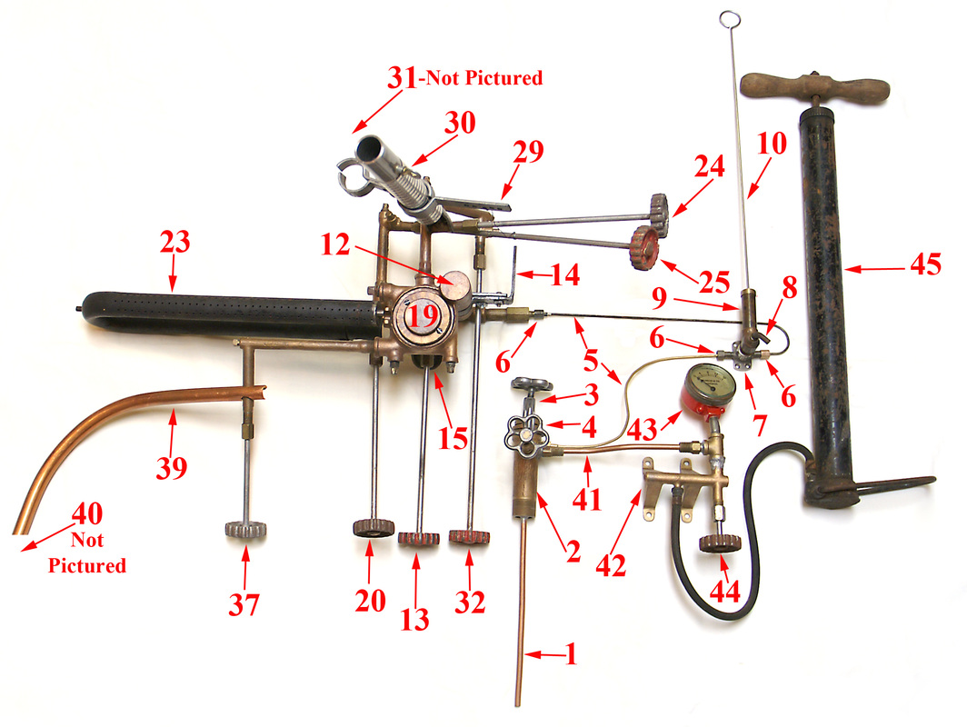
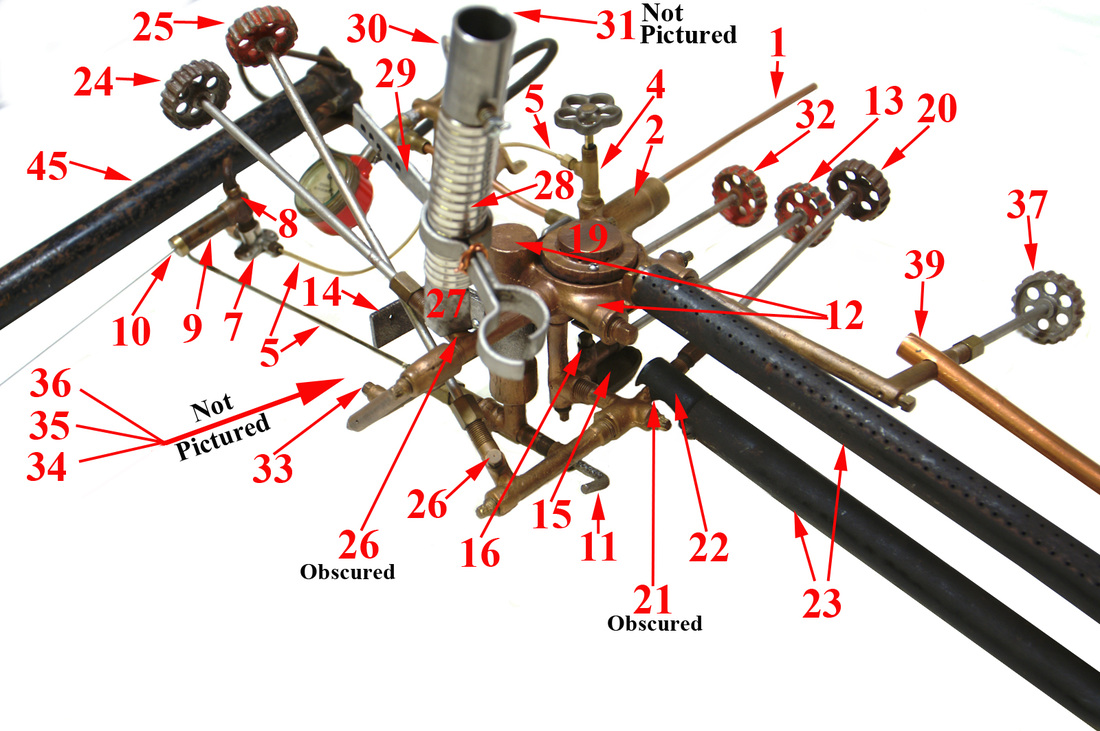
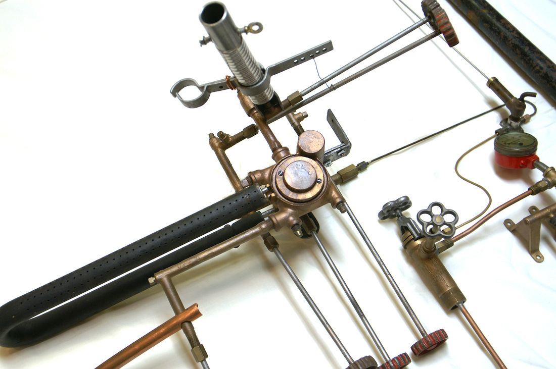
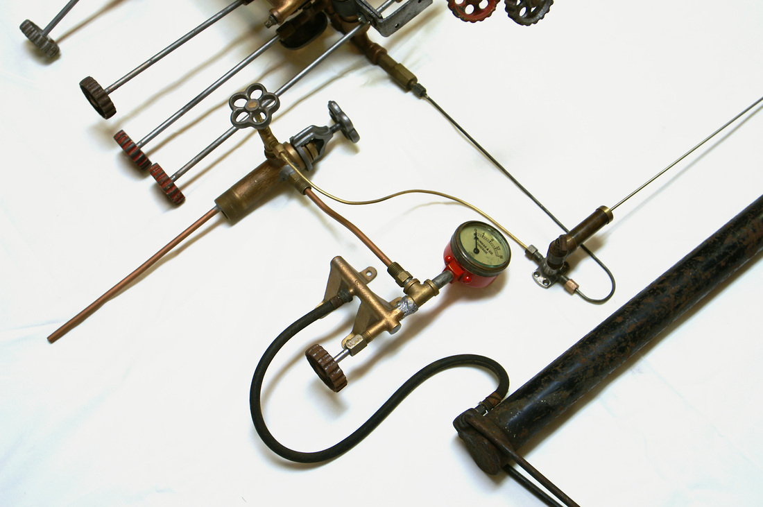
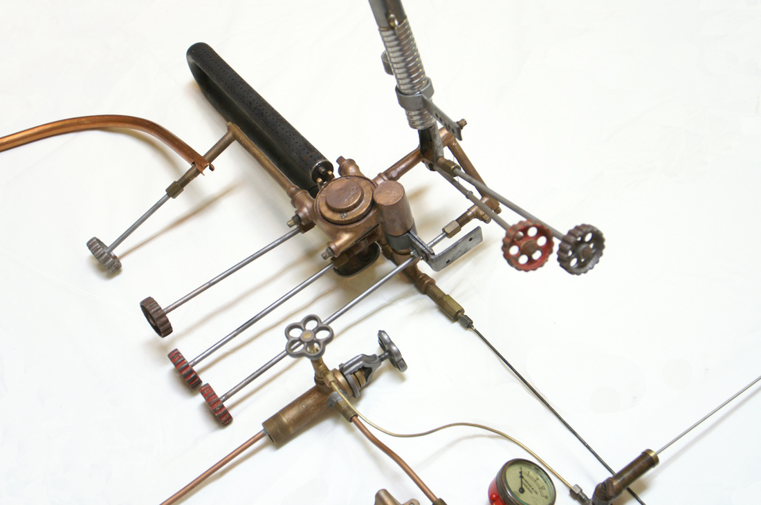
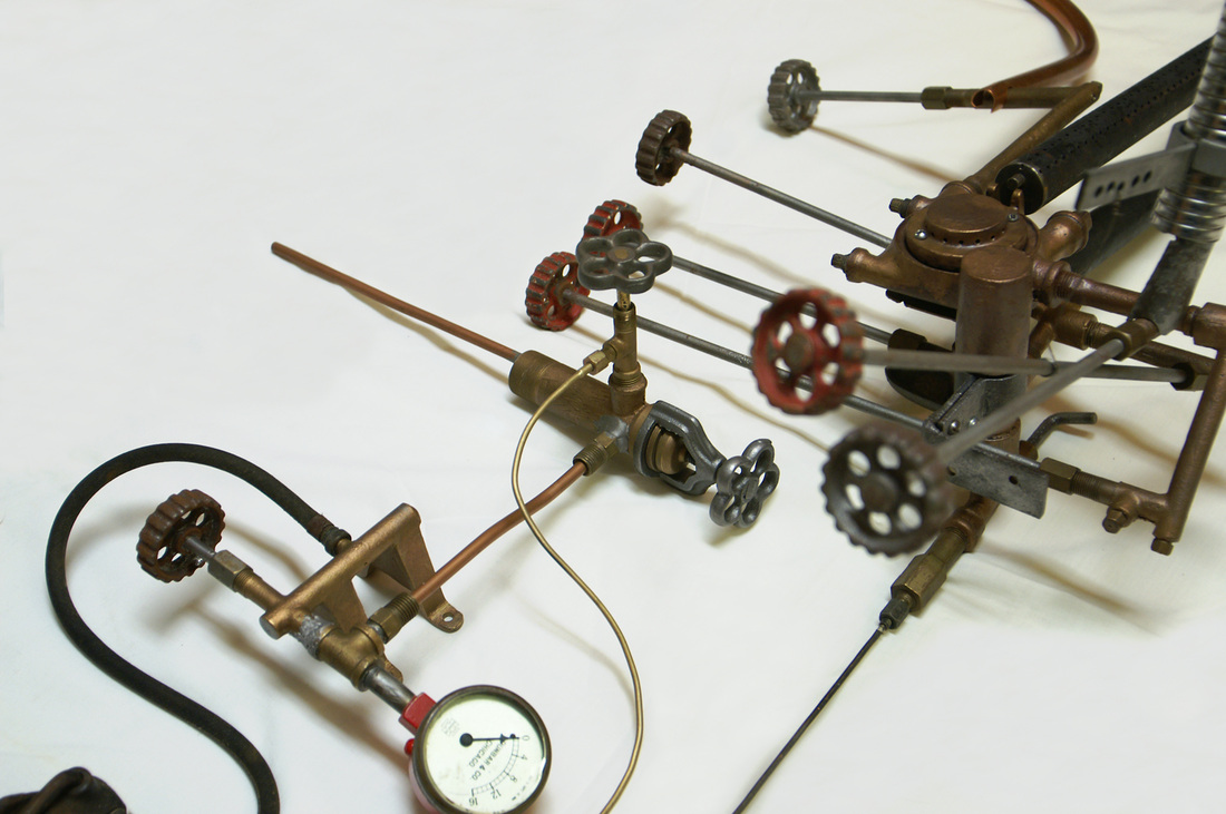
The MAJOR COMPONENTS of the system consisted of: A) the white gas tank, B) the hollow wire (Gloria Light Co product), C) the 0 to 4 pound pressure gauge, D) the air pump, E) the lighter assembly, F) the Dunbar & Co gas vapor generator with its assortment of valves and burner tips or jets, G) the air-gas vapor distribution tubes and metering valves, and H) burners: the boiler burner, the popper(s) burner(s), the peanut roaster burner, and the stove burner. A numbered index that names the parts is located between the first and second pictures below.
White Gas System Pictures
Unlabled pictures follow the labeled pictures
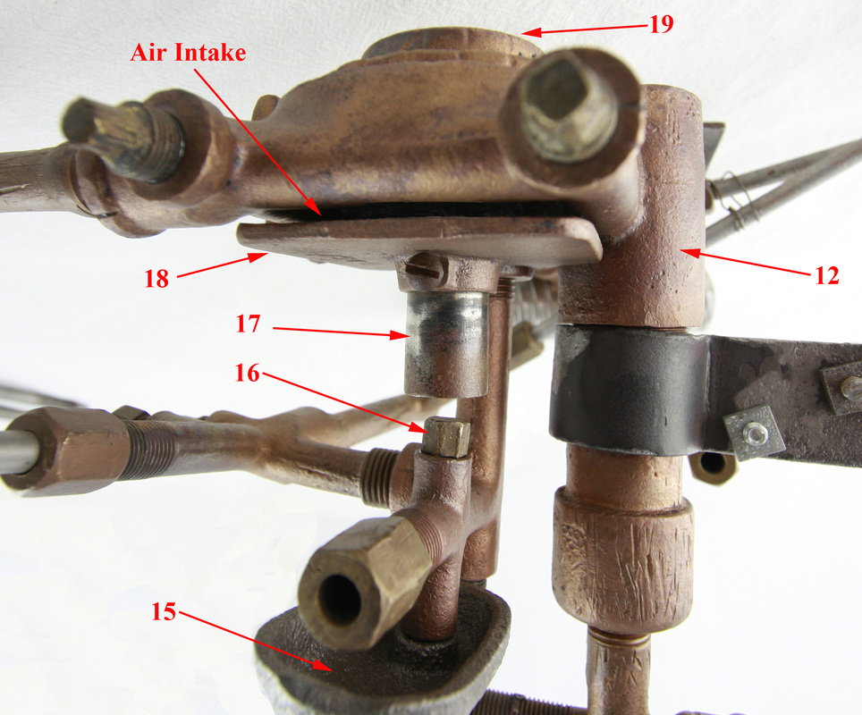
Index for all the White Gas Labeled Pictures.
We have attached a file that you can print out and then use the printed index to look at the pictures as it is hard to go back and forth on the monitor from the index to the pictures. Click on file just below this note to download and print.
| white_gas_system_index-2-1.docx | |
| File Size: | 14 kb |
| File Type: | docx |
1) Pickup Tube: Liquid White Gas (Gloria Light Company)
2) Filler Pipe: White Gas (Gloria Light Company)
3) Cap: Filler Pipe Unvented (Gloria Light Company)
4) Valve: White Gas (Gloria Light Company)
5) Hollow Wire (Gloria Light Company)
6) Tapered Flare Fitting (Gloria Light Company)
7) Lighter Mounting Base (Dunbar & Co)
8) Valve: Lighter Tap and Base (Dunbar & Co)
9) Lighter Cup (Dunbar & Co)
10) Lighter (Dunbar & Co)
11) Valve: Gas Vapor Generator Pressure Regulating
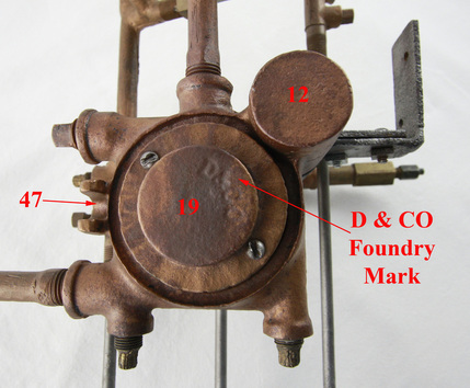
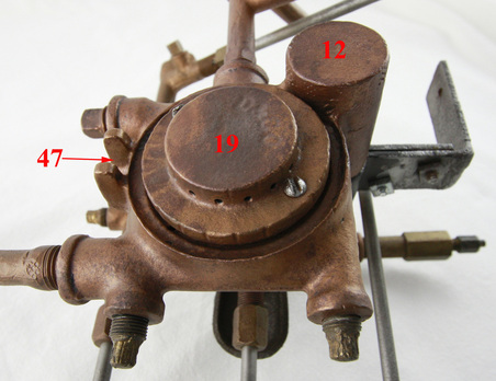
12) Gas Vapor Generator
13) Valve: Gas Vapor Generator
14) Mounting Bracket: Gas Vapor Generator
15) Drip Cup: Iron Liquid Gas Cup
16) Jet (Burner Tip): Gas Vapor Generator Jet (#78--- .016”)
17) Gas Vapor Distribution Tube for Gas Vapor Generator Burner
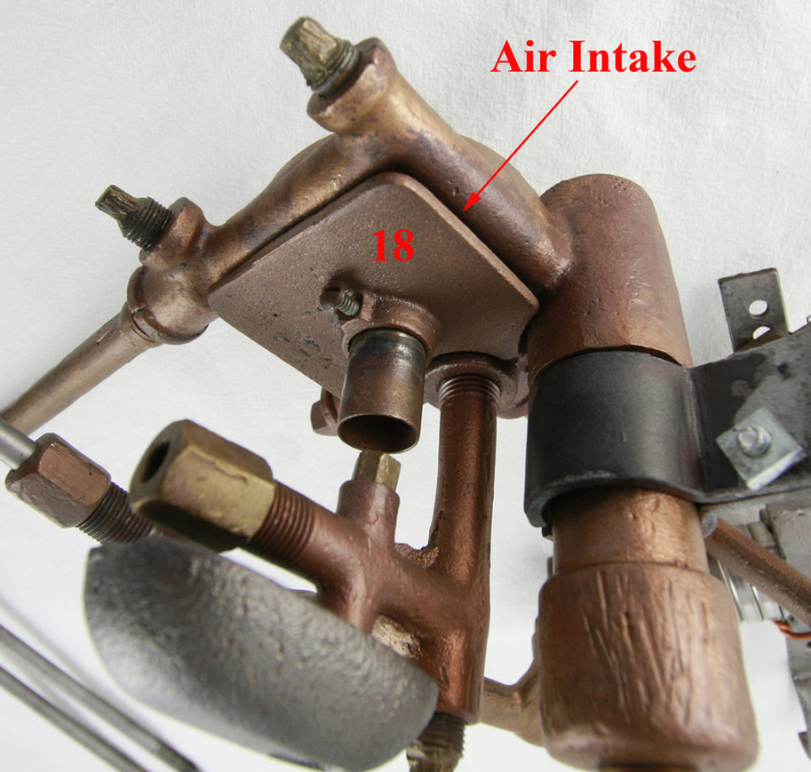
18) Air-Gas Mixer Plate for Gas Vapor Generator Burner
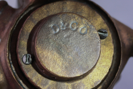
19) Gas Vapor Generator Burner
20) Valve: Gas Vapor Main Boiler Burner
21) Jet (Burner Tip): Main Boiler Burner (#71---.026”)
22) Air-Gas Mixer: Main Boiler Burner
23) Main Boiler Burner
24) Valve: Rotary Air Popper Burner
25) Valve: Rotary Air Popper Burner)
26) Jets (Burner Tips): Rotary Air Poppers (#71---.026”)
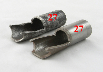
27) Airgas Mixer: Rotary Air Popper
28) Flexible Air-Gas Distribution Tube for Rotary Air Popper
29) Bracket: Air-gas Delivery Tube
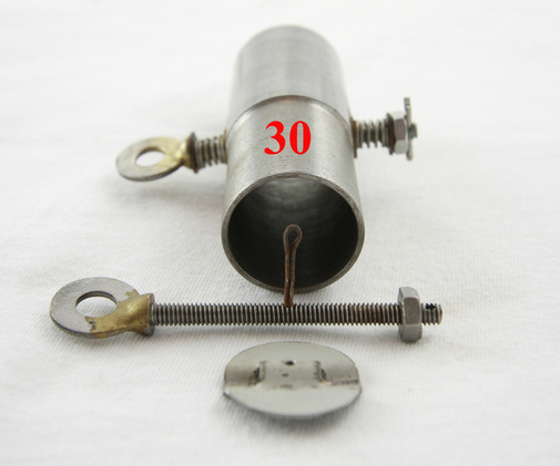
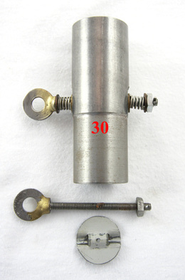
30) Valve: Butterfly Air-gas Rotary Air Popper
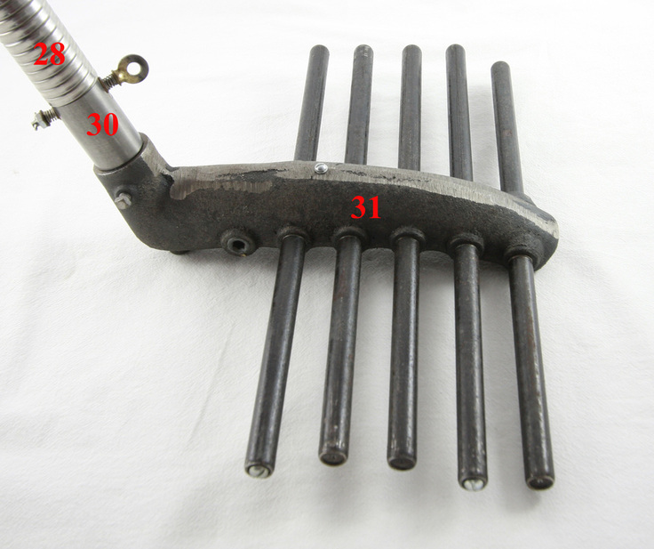
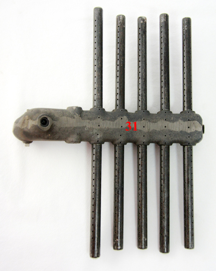
31) Burner: Rotary Air Popper
32) Valve: Peanut Roaster Burner
33) Jet (Burner Tip): Peanut Roaster (#71---.026”)
34) Air-Gas Mixer: Peanut Roaster
35) Pipe: Air-Gas Distribution for Peanut Roaster
36) Burner: Peanut Roaster
37) Valve: Stove Burner
38) Jet (Burner Tip): Stove Burner (#78---.016”)
39) Airgas Mixer and Distribution Tube for Stove (Copper)
40) Burner: Stove
41) Air Pressure Supply Pipe
42) Air Pressure Manifold
43) Air Pressure Gauge
44) Air Pressure Supply Valve
45) Air Pressure Pump (Automobile Tire Pump or Gloria Light Company Pump)
46) Schrader Tire Stem Thread (without the Valve) for the Pump
47) Bracket Support Main Boiler Burner
Valve: Butterfly Air-Gas Rotary Air Popper - Exact Reproduction
Burner: Rotary Air Popper 12 by 15 manufactured by Dunbar Manufacturing
The Following Pictures are Additional Views and Closeups of the White Gas System
Alternate Air Pressure Manifold
